


Table of Contents
To optimize the useful life of the components of the undercarriage, it is very necessary to know the state of each of the components, especially the state of wear, since due to the wear that occurs in each components of the undercarriage can be overloaded, by knowing the state of the components can be made decisions about the change or the reconstruction of the same. Which allows the useful life to be extended.
There are various methods, equipment, and techniques to be able to know the state of wear of the components of the undercarriage, as a rule to be able to measure wear it is necessary to be very meticulous when making the measurements, sometimes several measurements will be necessary of which an average must be made to have a more precise value.
For each element, the measurement and the technique for measuring wear is different, since it depends on the structure, then the measurements to various components of the undercarriage will be analyzed.
MEASUREMENT TECHNIQUE
There are two measurement techniques for track links, the measurement can be performed with a depth gauge or with an ultrasonic wear indicator.
With the depth gauge technique, the height of the link must be measured from the rail surface to the track shoe. The measurement succeeds when it is located outside the links at the end of the track pin. The depth gauge should be placed as close as possible to the end of the past, verifying that the links and the surface of the shoe do not have dirt or adhering elements. The measurement should be accurate to 0.01 in or 0.25mm.

On the other hand, with the ultrasonic wear indicator technique measure the distance from the rail surface to the bushing hole, you need to place the probe in the link above the center line of the bushing and slide the probe along the surface of the tread for the smallest reading.

WEAR LIMITS
To establish the link wear limits, you must start by establishing an allowable wear that is equal to a fraction of the free space between the link and the idler. On certain machines, this space is located between the shoulder of the link pin and the flange of the idler. On the other hand, in other types of machines the free space is between the hub and the internal flanges of a double flange idler.
In the case that you have a 100% worn link with a idler in the same situation, the flanges of the idlers will be in contact with the projections of the link pin or with the bushing, from 100% onwards the wear of the pin of the link. The link fails, thus reducing the retention of the past, and wear on the bushings can cause cracks to occur.
WEAR LIMITS: MAJOR AND MINOR
The remaining resistance to cracking indicates the wear limit of the sealed and lubricated chain links.
In the ultrasonic measurements, tables will be shown that show that the link rail is always thicker which leads to it being more resistant to cracking in the column with the lowest allowable wear compared to the column with the highest allowable wear. Your correct selection of the optimum allowable wear column will maximize link life and prevent cracking. The resistance to cracking depends on several factors, among which are the position of the sprocket (high or low), the conditions of the ground where it is operated, the useful life of the link and the type of operation that is carried out.
ASSEMBLY AND TIGHTENING PROCEDURE
The correct assembly and tightening sequence will ensure that the master link will have a useful life in accordance with that established by the manufacturer, in addition to ensuring the integrity of the bolted joint, for which it is necessary to correctly follow the specified procedure. You should consider that the five-tooth and single-tooth twist angle values are different as the bolts have different threads.
- Before the installation of the track, it is required to clean the connection point of the master link, verify that it does not present any type of damage, remove all the paint.
- A release compound should be applied to the bolt threads, body, washer face, and bolt contact areas on the shoe during assembly.
- Bring the master links together and make sure the alignment of the king bolt holes. Install a kingpin on each link. When turned by hand, the bolts should not present any resistance and should turn easily in the threads.
- Remove the screws. Install the master chain shoe and 4 master bolts. Turn the kingpins by hand.
- Tighten the king bolts, the torque indications should be found in the equipment manual.
SEALED AND LUBRICATED CHAIN BUSHING
MEASUREMENT TECHNIQUE
To be able to make a measurement, the chain bushing is the most relevant component. It can be done in 3 ways; each method uses different tools. You should consult to find out which method is the most appropriate in your case, since for example the depth gauge tool only provides wear based on the vertical position.
1. ULTRASONIC WEAR INDICATOR METHOD
It is considered that among the exposed methods this is the most accurate because it makes the dimension precisely in the most critical dimension, which is the thickness of the bushing wall, it is done by slowly sliding the probe around the reverse, vertical and reverse transmission sides. front, it needs to be the smallest dimension as this indicates wear.

2. CALIPER METHOD
In this method, the diameter of the bushing is measured, it is strictly necessary to clean and perform the technique properly because, due to a bad measurement, the diameter value can vary greatly from the real value, leading to the conclusion that the wear has been very high. accelerated, the most common errors in this measurement are:
Calipers too tight: Calipers that are too tight causing the measurement to be less than actual.

Calipers at the wrong angle to the hub axis: They will cause a measurement that is larger than the actual one.

Calipers that do not slide back and forth at position to be measured: Final reading will be lower than actual.

The bushing was not cleaned well before measurement: If the surface of the bushing is not clean, the measurement will be larger than the original due to adhering residue.

Calipers not placed in the most worn part of the hub: If the gauges are placed in this way, the measured value will be lower.

It is recommended that to make the wear measurement the bushings are removed from the track; the measurement must have an accuracy of ± 0.01 in. (± 0.25 mm).
3. DEPTH GAUGE METHOD
It uses the same depth gauge that is used for links. This is a more error-free method compared to others; however, it may not be 100% accurate and may be subject to minor dimensional differences. In addition, it is a technique that requires a lot of care and precision on the part of the meter. Among the most common mistakes are:
- Dirty component
- The base of the depth gauge is incorrectly positioned with respect to the length of the bushing.
- The depth gauge probe is not positioned correctly so it does not make a 90 ° or perpendicular angle with the shoe.

DISADVANTAGES OF THE DEPTH GAUGE METHOD
It is impossible to perform a forward or reverse drive side wear measurement which is extremely necessary for many applications.
ADVANTAGES OF THE DEPTH GAUGE METHOD
The rear of the hub can be measured after turning the hub.
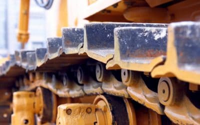
TRACK SHOE
MEASUREMENT TECHNIQUE
In the track shoe, only the wear of the claw can be measured because it is for the only thing that there are reference values for comparison. Plate thickness can be measured and compared to a new component to determine wear. Both the depth gauge and the ultrasonic wear indicator can be used on the track shoes.

Using the ultrasonic wear indicator, the measurement should be made between the claw tip and the bottom of the plate, 1/3 of the way from the end of the track shoe should be taken and the probe can be placed on the top or bottom. Measurements must be made with a precision of 0.02 in. or 0.5 mm.

WEAR LIMITS
Track shoe wear limits are based on 3 criteria, listed below in order of importance:
- Track shoe with resistance to bending.
- The track shoe base must be readily available for reuse purposes.
- Remaining traction-penetration capacity of the track shoe to achieve a required production capacity.
TRACK SHOE CAUSE AND EFFECT: PERFORMANCE
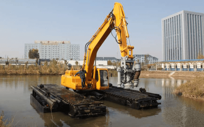
The track shoe is the component that is most affected by the soil conditions and the handling of the machine due to greater wear and tear and the structure is compromised, reducing its useful life compared to any other component in the system of the undercarriage. On the other hand, the correct selection of the type of track shoe, as well as its width, has a really big impact on the performance of the equipment in general and the performance of each component of the undercarriage.
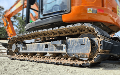
INSTALL THE TRACK SHOES PROPERLY
If the track shoe becomes loose, the main reason is that the hardware of the track shoe is poorly tightened. Next, a small procedure is shown to tighten the bolts, a constant revision must be carried out every 50 to 100 hours of operation of the equipment, sometimes it also depends on the expertise of the operator, if necessary, it should be ruled out that the problem of the track shoe is due to a bad tightening.
- Remove all rust and paint from link and track shoe mating surfaces.
- Lubricate the bolt threads and bolt washer faces.
- Tighten the bolts to the specified torque.
- Apply an additional 1/3 turn to each bolt.
It is necessary to give an additional 1/3 of a turn to the bolt because it causes it to stretch properly and improves retention, in the stretching of the bolt there is a permanent deformation in the bolt that ensures that the maximum clamping force of the bolt is used.
IDLERS: CONVENTIONAL IDLERS
MEASUREMENT TECHNIQUE
There are 2 measurable wear positions on the idlers, the first on the tread and the other on the center flange. Tread wear can be determined using a measurement using the depth gauge from the center flange of the tread surface. A measurement should be taken on both sides of the center tread and the measurements are averaged. The biggest error in measuring idlers tread wear arises from wear on the center flange that alters the set point. If you consider that this wear exists, you should try to compensate it in the measure taken. You must remember that idlers tread wear measurements increase decreases as center flange wear occurs.

The wear of the center flange can be measured using the ultrasonic wear indicator. It measures the thickness of the center flange and should be taken directly in the center of the flange. Use the conventional depth gauge to measure wear on the tread surface, then add the center flange wear to the depth gauge measurement before determining the percent worn.
WEAR LIMITS
Idler tread wear limits are based on two basic criteria: the rebuildability of the tread surface plus the space between the center flange and the track bushing. If the idler wears more than 110%, the tread will become too thin to be rebuilt successfully.
REBUILDABILITY
The roll belt and flange can be rebuilt (a screed operation is used) successfully multiple times if they are not worn beyond the service limits and if the center flange wear is considered at this service point. The idler generally provides a life equal to the life of the original tread up to the respective limits if welded to the original dimensions.
FREQUENTLY ASKED QUESTIONS (FAQ SECTION)
HOW LONG IS IT NECESSARY TO MEASURE THE WEAR OF THE COMPONENTS OF THE UNDERCARRIAGE?
There is no set time, the performance of measurements depends on many factors such as variables that are not controllable by the operator, such as the type of soil and the number of turns that are made, a machine that is on a soil without Irregularities you will not need to measure wear as frequently as a machine that works on slopes with rocky or uneven ground, visual inspections should be carried out whenever possible at the end of the use of the equipment.
And preventive maintenance must be scheduled in which wear measurements can be made, which is common every 50-100 hours of use. As mentioned before, in the case of extreme conditions, wear will appear much faster, in those cases it is necessary to evaluate which side of the undercarriage is the most worn and evaluate whether it is feasible to change components from one side. the other until the wear of both is equal or if the parts simply need to be replaced.
0 Comments